Hull and fins
Added mass, drag, hull lift at incidence, and fin lift and stall, including the hull's effect on the fins.
AUV mission simulator
A six-degree-of-freedom simulator for autonomous underwater vehicles. Lay out the vehicle, plan the route over the charted seabed, and watch the autopilot fly it, with the physics checked against published test data.
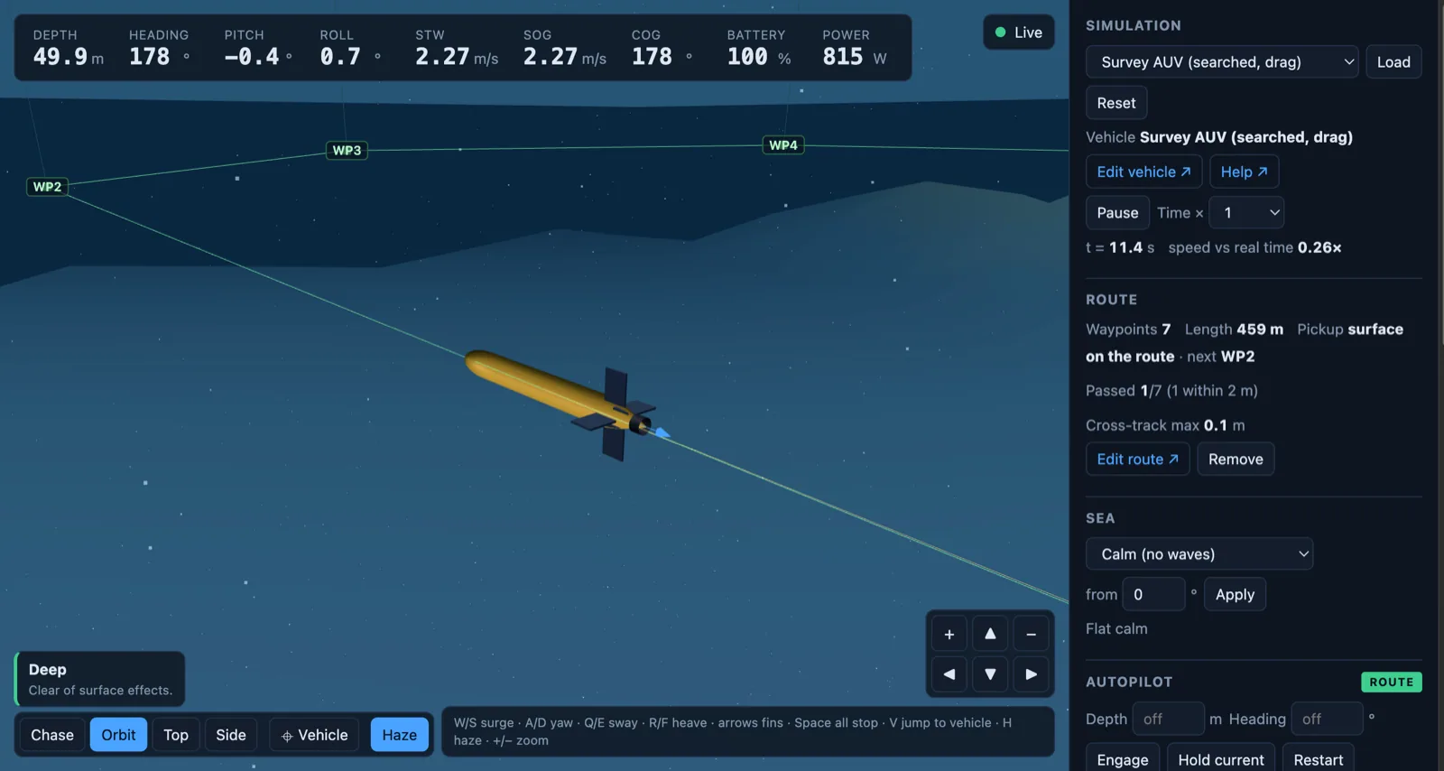
See it fly
A 430 kg survey AUV turning at a waypoint at 50 m. It banks into the turn and rolls level on the next leg, while the panel tracks waypoints passed, cross-track error, battery and power.
How it works
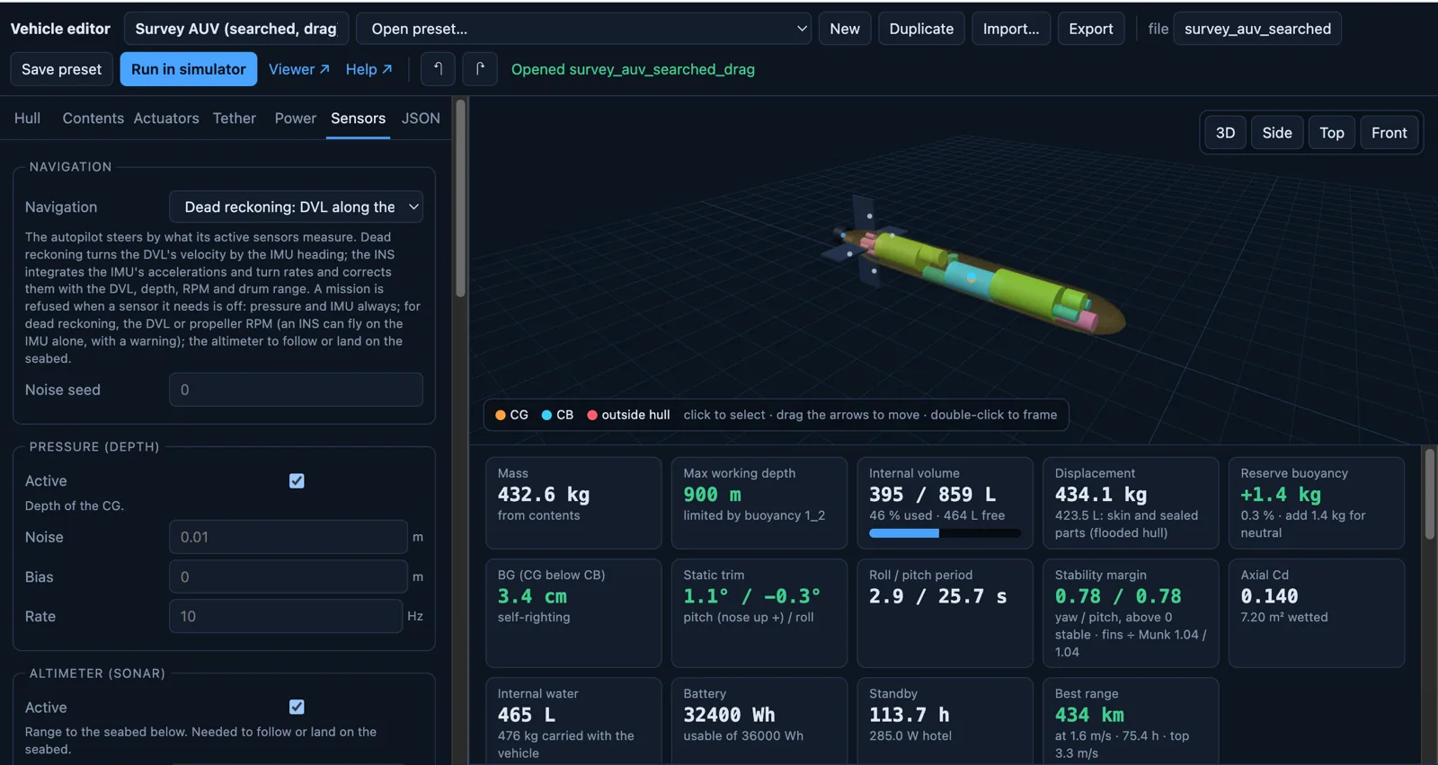
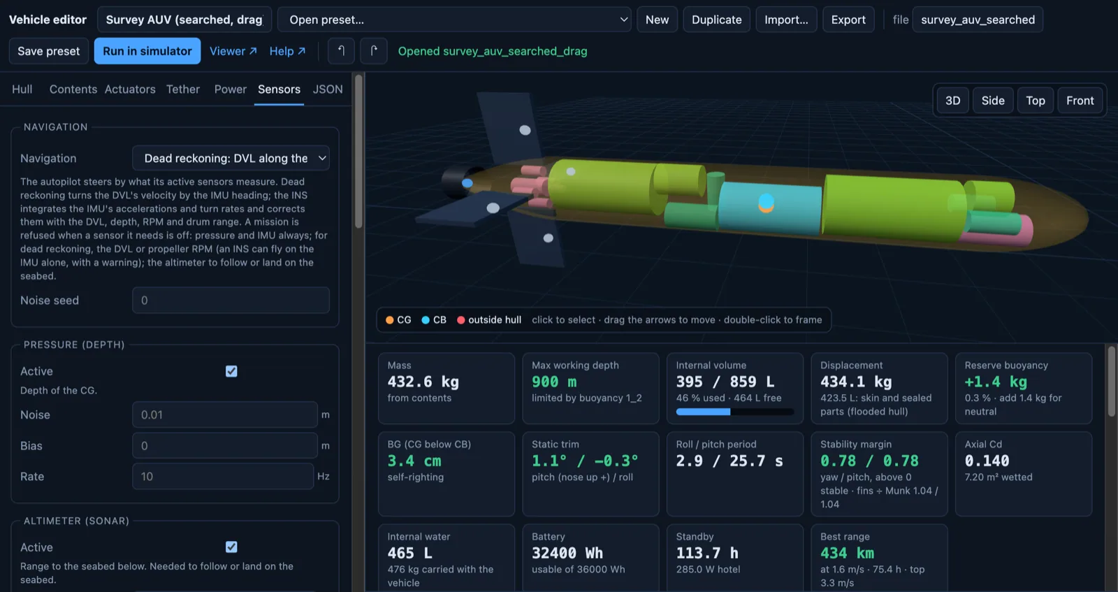
Shape the hull, place batteries, electronics and payload inside it, and add fins, thrusters, a tether, power and sensors. As you work, the editor shows mass, displacement, reserve buoyancy, centres of gravity and buoyancy, static trim, roll and pitch periods, stability margin, working depth, battery endurance and best range.
Or let the AI-based design optimizer lay it out. Give it the parts and the rules, and it searches thousands of arrangements: it orders the parts, sizes the buoyancy and the pressure housings, wraps the hull around them, and keeps the design with the lowest drag, the longest range or the tightest hull that still balances, trims and stays stable. The survey AUV on this page came out of 5,600 layouts searched in 24 minutes.
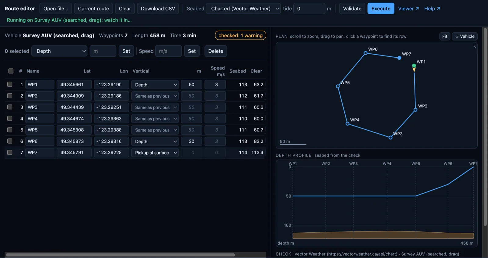
Set waypoints by position, then depth or altitude above the seabed, speed, and a pickup at the surface. Each leg is checked against the charted seabed and the tide before the mission runs, with the clearance at every waypoint and a depth profile of the whole route.
Vector Weather is built into the simulator: the seabed comes from its charts, and you can test the mission against its current and weather forecasts up to 15 days ahead, to choose the day before the vehicle goes in.
The autopilot flies the route from what the vehicle's own sensors measure, not from the true position, so navigation drift shows up as it would at sea. Watch in 3D from any angle, add waves and currents, or take the controls yourself.
What it models
Added mass, drag, hull lift at incidence, and fin lift and stall, including the hull's effect on the fins.
Propellers and thrusters with their power limits, hotel load, battery energy, endurance and range.
Each part's weight and displacement, flooded and sealed spaces, trim, stability, and the depth each housing is rated to.
Dead reckoning or a strapdown INS by IMU grade, aided by DVL, depth, propeller RPM or tether range, each with its own noise.
Depth, heading and track following, sharing the fins and thrusters out by what each one can actually do.
Waves, currents, suction and wave drag near the surface, and the charted seabed under the vehicle.
A tether or towed cable modelled along its length, with a winch, for tethered vehicles and towbodies.
Added mass and damping fitted to a logged run of your own vehicle, so the model behaves like the real one.
Checked against data
Each part of the physics is compared with published tests, with a raw run and a script that reproduces it.
| Model | Checked against | Result |
|---|---|---|
| Hull and fin forces | Captive-model tests on the SUBOFF benchmark hull; Roddy (1990) | Side force and yaw moment within 1–15 %; stern-plane control forces within 5 % |
| Near the surface | Farell & Güven (1973); SUBOFF tank and CFD resistance | Wave drag and total resistance within about 15 % from one hull diameter down |
| Fitting to a logged run | Runs with known coefficients and sensor noise | Added mass within 3 %, damping within 5 % from 10 minutes of noisy data |
| Pressure-hull depth | Windenburg & Trilling (1934), 36 collapse tests; EN 13445-3 | Ratings below every measured collapse, by at least 1.7× |
| Towed cable | Vaz & Patel sea trials, 300 m armoured cable | Mean position error about 5 % of the distance from the towpoint |
| Navigation drift | The simulator's true position, 0.3 m/s current, DVL bottom lock | After 260 s: 1.8 m dead reckoning, 1.2 m tactical INS, 0.11 m navigation-grade INS |
Not yet validated
The hull's own yaw damping (still 14–24 % low), sideways forces near the surface, hulls other than SUBOFF for the fitted constants, and blunt or open-frame vehicles, except by fitting a logged run.
Simulation results are provided for planning and information. Where a result informs a design or safety-critical decision, it is reviewed by a partner professional engineer.
Go deeper
How the optimizer explores layouts, fins, propellers and thrusters, what it forecasts for each, and two ways to work with us. PDF included.
Read moreHow the search trades drag against dry mass, which hull shapes it covers and how far each is validated, and what flat-bottomed hulls need. PDF included.
Read moreSend us the vehicle's layout, the mission, and the site. We'll tell you what the simulator can answer.